Tennis court line detector: Part 1, synthetic data generation

Disclaimer: unfortunately, this project did not produce decent results. I decided to publish it anyway, because there are a few nuggets of knowledge I learned along the way that I wanted to share to other computer vision enthusiasts. I'm also holding onto some hope that someone will come along and give me some ideas on how to come up with a better solution. If you're looking for a project with a working solution, "move along, there's nothing to see here"
Here is the challenge: build a robust tennis court line detection algorithm which could form the basis of a ball tracking system, similar to what is offered by SwingVision. Knowing where the tennis court lies in the image would allow the overall algorithm to determine if the ball landed in or out of bounds.
There are several ways to go about this, as described in Bart Timmermans blog post Improving Tennis Court Line Detection with Machine Learning
- Hough transform (traditional CV)
- Deep learning CNN
- Hybrid approach which uses a CNN and a Hough transform for post-processing
However, there were a few things missing from Bart's blog post which I will try to address:
- No dataset is provided
- No codebase is provided
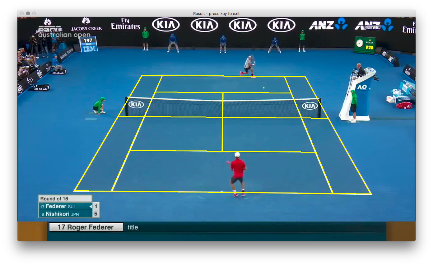
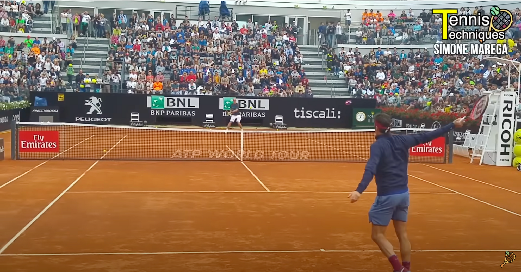
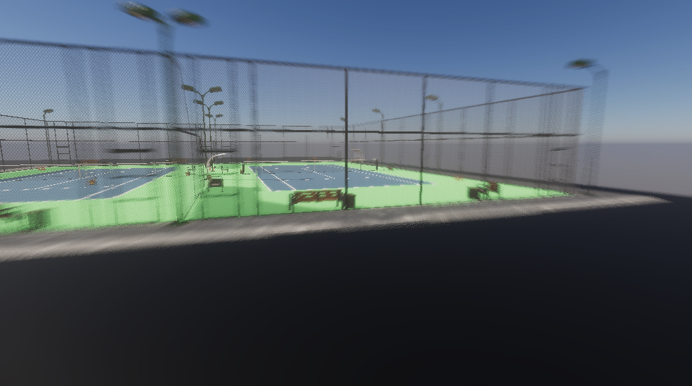
- How does the model handle images where only part of the court is showing, as shown below?
This blog post will attempt to address those using synthetic data.
The overall plan
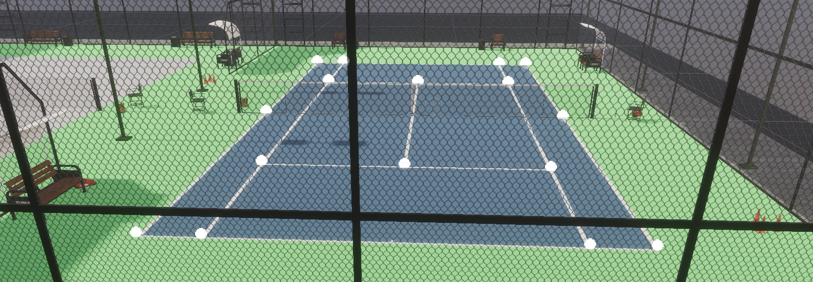
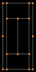
I decided to take the same overall approach described in Improving Tennis Court Line Detection with Machine Learning, which requires training on CNN with a labeled dataset of tennis courts, where each tennis court is labeled with 16 key points as follows:
Unfortunately there doesn't seem to be existing dataset of tennis courts labeled with such key points.
Hand-labeling a large dataset of tennis court images would be tedious, or expensive via labeling service. An alternative is to generate a synthetic dataset instead.
The overall plan:
- Generate a synthetic dataset
- Train a CNN on the synthetic dataset
- Collect a small hand-labeled dataset (~200 images)
- Perform Sim2Real by fine-tuning the synthetic-data trained CNN model on real images
Finding a software package to generate synthetic datasets
Option 1: Google Kubric
Google has released a very impressive open-source project for scripting synthetic datasets: Google Kubric
It seems very easy to import objects from ShapeNet, Google Scanned Objects (GSO), and a few other asset repositories. However, I decided not to use Kubric as I didn't see a clear path to use Kubric to import 3D models of tennis courts with the required key points added to the model.
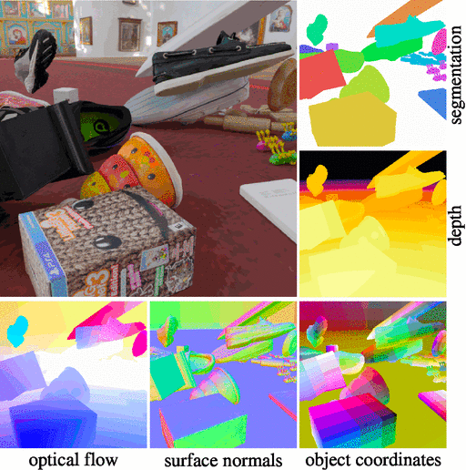
Option 2: Unity Perception
Unity ships with the Perception Package, which gives generic low-level primitives for generating synthetic data in the SOLO annotation format. SOLO offers exporting utilities to other common formats, such as COCO.
Unity Perception supports many different labeler types, such as 2D Bounding Boxes and a Keypoint labeler, which is what is needed for this project.
The documentation and support seems to be very comprehensive, including a great series of getting started tutorials.
Tennis court models in Unity Perception
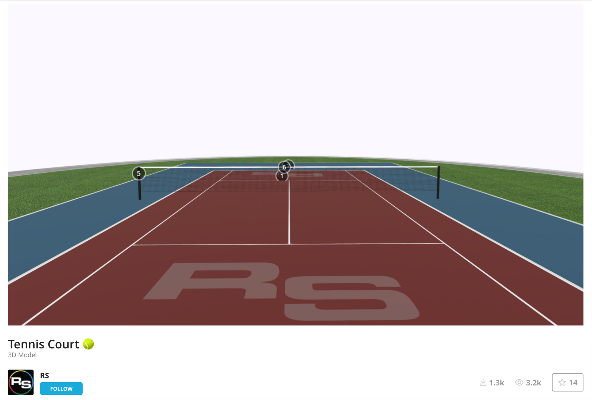
Step 1: Download a tennis court model from Shapeway
This is a very basic tennis court 3D model, but it should serve as a good starting point to get the data generation pipeline running.
I chose this model because it has an .fbx download option, which makes it very easy to import into Unity. (some of the other formats, like .blend, can be a lot more challenging to import into unity)
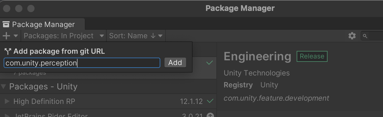
Step 2: Import unity perception package
In the package manager, add com.unity.perception under "Add package from git URL"
Step 3: Define a keypoints template
Create a new KeypointTemplate by right clicking in Assets and choosing 'Create->Perception->Keypoint Template'
Create entries in your new keypoint template for all of the keypoints that you want to track.
With two out of the sixteen total tennis court keypoints added, it looks like this:
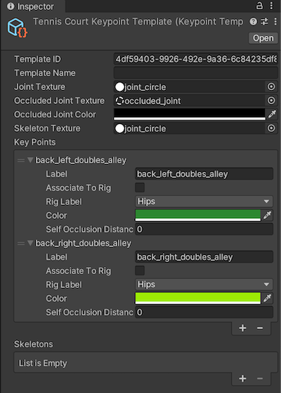
Notes on the above screenshot:
- Make sure to set Joint Texture to "joint_circle", as well as setting Occluded Joint Texture. I'm not sure if Skeleton Texture matters.
- There's no need to check the Associate To Rig checkboxes. Ignore the Rig Label field as well.
Here is the list of keypoints used (these aren't standard, I just made up these keypoint names)
back_left_doubles_alley
back_right_doubles_alley
back_left_inside_doubles_alley
back_right_inside_doubles_alley
back_right_service_box_corner
back_right_service_box_tee
back_left_service_corner
center_right_net
center_left_net
front_right_service_box_corner
front_right_service_box_tee
front_left_service_corner
front_right_doubles_alley
front_right_inside_doubles_alley
front_left_inside_doubles_alley
front_left_doubles_alley
Step 4: Add empty game objects associated with keypoints to model
Create game objects (no geometry is needed to be associated to them) for the points of interest that you want to track and put them in the scene where they should be.
Here is an example of creating two empty game objects for two of the tennis court corners. Because the Joint Texture is set to "joint_circle", they show up as spheres in the editor.
It's very important that these are created as sub objects of the model (in this screenshot, the tennis court model was imported as "4"), otherwise it won't work.
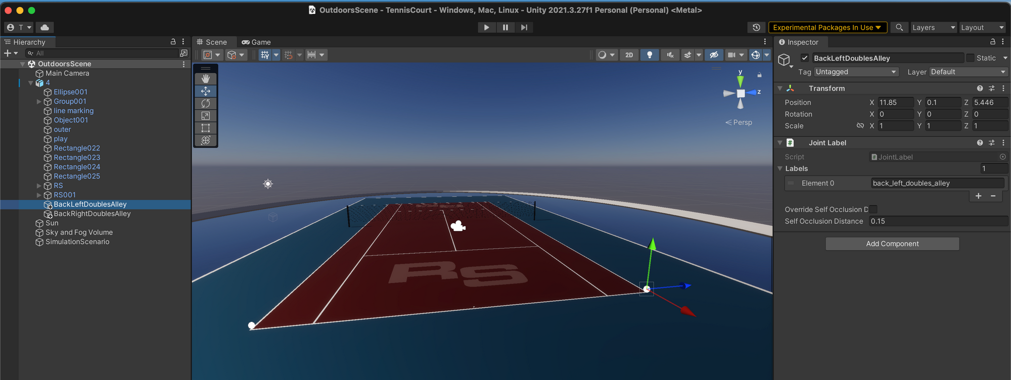
Add a JointLabel to each of these new game objects. Hit Add Component, search for and choose JointLabel, and then add a label that corresponds to the label used in your keypoint template defined above.
Notice in the above screenshot the Y value is set to 0.1, slightly above the surface. This is important if you want the visibility state to be set to 2 - in my experience if it was set to 0.0 it will use a visibility state as 1, which is defined as:
1 denotes a joint that is inside of the image but cannot be seen because the part of the object it belongs to is not visible in the image
Step 5: Add a label ID file
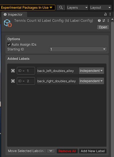
Right-click the Assets folder, then click Create → Perception → ID Label Config. Add the same labels as used in the keypoint template (sorry about the duplicated work, I don't know of a better way).
It should look like this:
Step 6: Add and configure a perception camera
See the unity perception tutorial for details.
Add a Keypoint Labeler to the Camera Labelers section, and associate the Active Template with the keypoint template created above, and the Id Label Config with the Id Label Config created above.
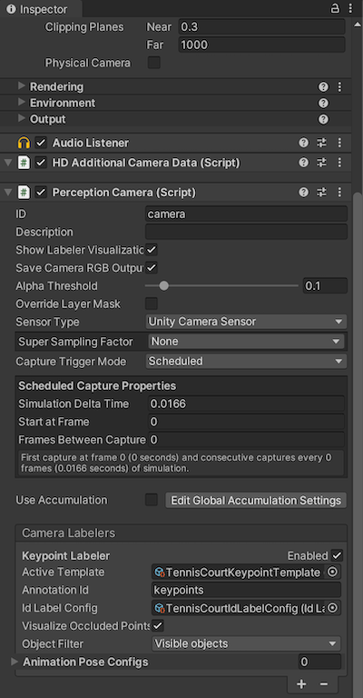
On your PerceptionCamera add your new KeypointTemplate to KeypointLabeler 'Active Template' field
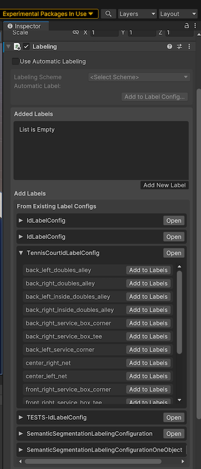
Step 7: Setup labeling on the tennis court
Select the tennis court mesh and in the Inspector choose Add Component / Labeling.
Then expand the TennisCourtIdLabelConfig, and for each keypoint label, click the Add to Labels button.
Alternatively, there is an option to use Automatic Labeling as described in this youtube video (I haven't tried it)
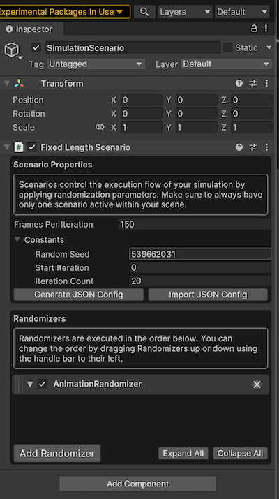
Step 8: Add a fixed length simulation scenario
Add a new empty game object to the top level of the scene, rename it to SimulationScenario, and add a Fixed Length Scenario component.
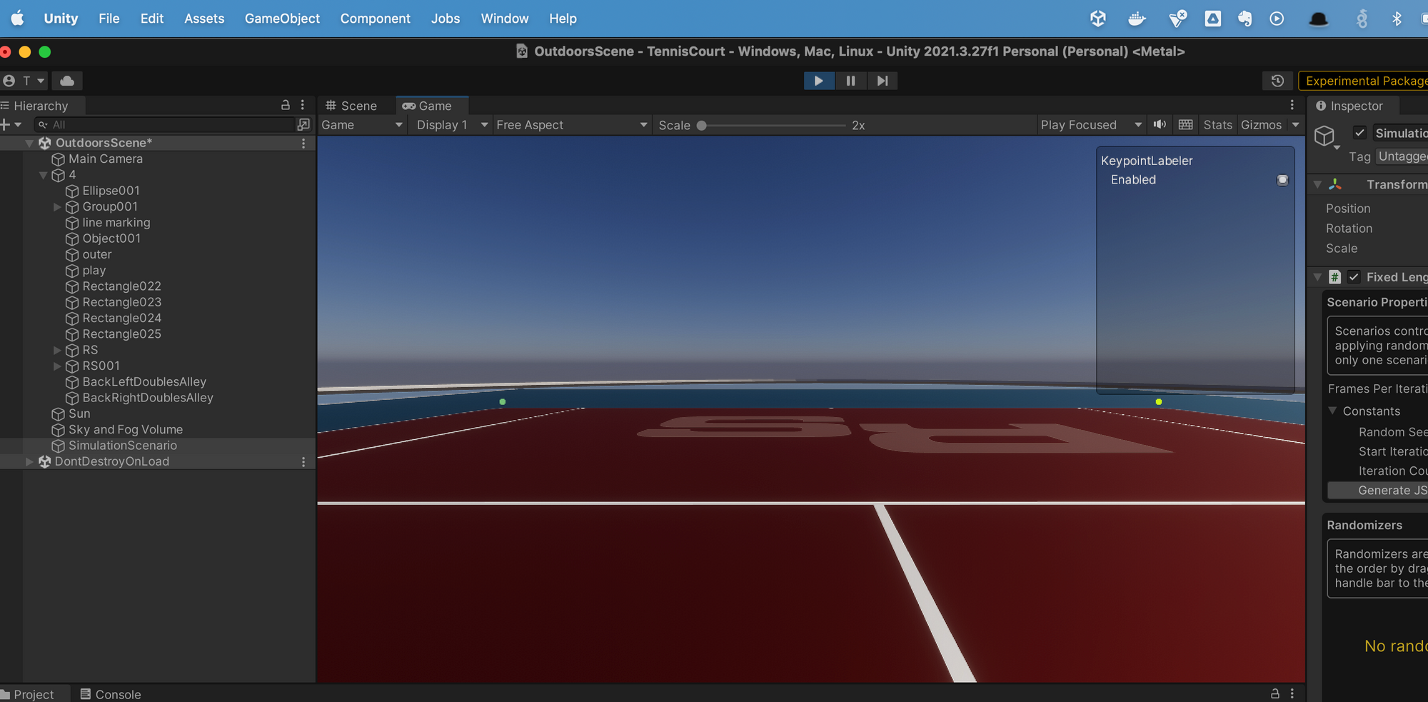
Step 9: Run scenario and inspect the output
Hit the play button at the top of the screen to run the scenario, and notice that your keypoints will show up with the corresponding colors set in the keypoint template file (different shades of green in this case)
To inspect the annotations, go to Edit / Project Settings / Perception, and click the Show Folder button.
Open the folder with the highest number, eg, solo_23, which will be the latest. Open one of the .json files under a sequence.x folder, and you should see the keypoint annotations with their locations in the image.
      "annotations": [
        {
          "@type": "type.unity.com/unity.solo.KeypointAnnotation",
          "id": "keypoints",
          "sensorId": "camera",
          "description": "Produces keypoint annotations for all visible labeled objects that have a humanoid animation avatar component.",
          "templateId": "4df59403-9926-492e-9a36-6c84235df8f1",
          "values": [
            {
              "instanceId": 1,
              "labelId": 1,
              "pose": "unset",
              "keypoints": [
                {
                  "index": 0,
                  "location": [
                    186.281342,
                    267.249481
                  ],
                  "cameraCartesianLocation": [
                    -5.113398,
                    0.127701953,
                    7.847996
                  ],
                  "state": 2
                },
                {
                  "index": 1,
                  "location": [
                    846.0371,
                    267.179169
                  ],
                  "cameraCartesianLocation": [
                    5.77259254,
                    0.1291088,
                    7.86311531
                  ],
                  "state": 2
                }
In this example, the keypoint on the left side is at (x,y) coordinate in the image of (186.28, 267.24)
The "state": 2 indicates that it is visible in the scene.
Adding randomizers
At this point, the dataset generated would only be a single annotated image. To generate a larger dataset from this tennis court model, Unity Perception supports the ability add randomizers for things like:
- Object(s) translation/rotation
- Lighting conditions
- Many more..
For now let's just add a rotation randomizer:
- Create and configure the rotation randomizer
- Associate the rotation randomizer label with the object you want to be rotated
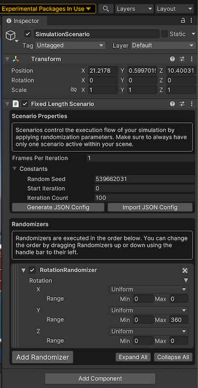
In the SimulationScenario object, add a RotationRandomizer with the following settings (it only "spins" around the y-axis)
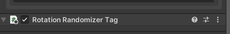
Then, in the tennis court object inspector, Add Component and choose Rotation Randomizer Tag. This creates the linkage with the rotation randomizer in the simulation scenario.
To avoid motion blur, you will also need to disable motion blur, as documented in Step 5 of the Unity Perception tutorial.
Now when you run the simulation, it will generate annotated images of the tennis court from various camera angles.
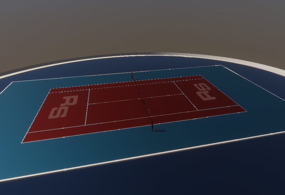
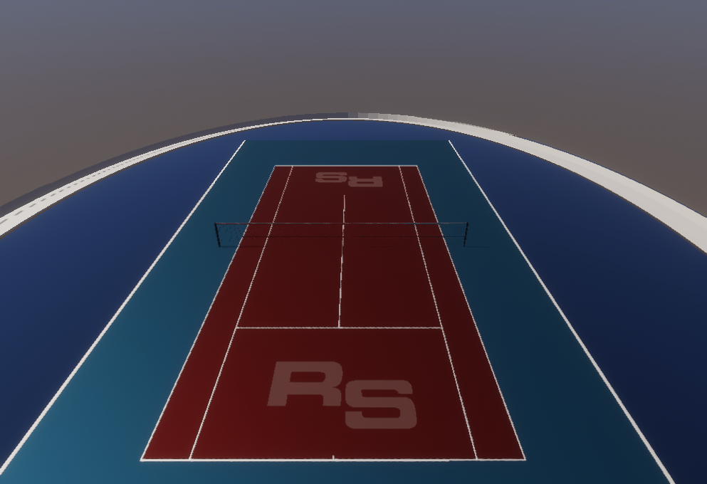
As mentioned earlier, the annotations for this dataset can be viewed by going to Edit / Project Settings / Perception, and click the Show Folder button.
Recap
We've now generated a labeled dataset of tennis court images with labeled keypoints, which can be used to train a CNN model.
Continue to Part 2 to see how to use this dataset to train the CNN.